Articles
| Name | Author | |
|---|---|---|
| White Paper: Continuing Improvement through Process Modelling and Adaption | Peder Falk, Aviation Systems Professional, Aviro AB | View article |
| Case Study: A Look inside manage/m | Dr. Falk Kalus, Director of the manage/m® division, Lufthansa Technik | View article |
| White Paper: Business Analytics for the Airlines MRO Industry | Lakshmi Narasimhan, Assistant Vice President – Travel & Transportation, and Sunil Joshi, Subject Matter Expert, Hexaware Technologies | View article |
| Case Study: New IT for MRO, the build or buy dilemma for AirAsia | Juswil Adriani, MRO Liaison Engineer, AirAsia | View article |
| White Paper: Mobile Device Considerations for Supply Chain and ERP Related Systems | Byron Clemens, President/Principal Consultant, CKK Solutions | View article |
| Case Study: Getting the right people in the right place for each job on the schedule | Dr. Orkun Hasekioglu, CIO, Turkish Airlines Technic | View article |
Case Study: Getting the right people in the right place for each job on the schedule
Author: Dr. Orkun Hasekioglu, CIO, Turkish Airlines Technic
SubscribeGetting the right people in the right place for each job on the schedule
The application of Wireless Sensor Network Technology, says Dr. Orkun Hasekioglu, CIO, Turkish Airlines Technic, has improved resource utilization and efficiency at Turkish Airlines Technic MRO
At Turkish Airlines Technic we have improved workflow and resource utilization by using a sensor network as an integral component in the allocation, resourcing, monitoring and recording of each task. A sensor network is a data communications network comprising a large number of mobile or stationary nodes that can communicate as well as sense and process data. A typical sensor network as described is depicted in Figure 1.
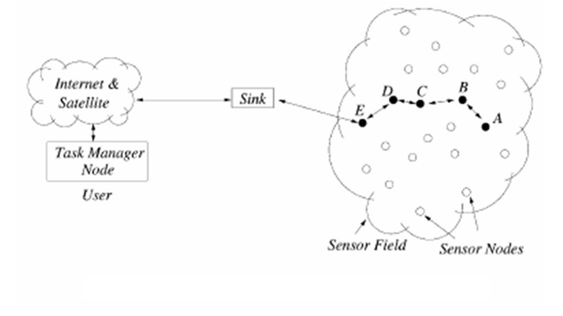
Figure 1
The number of randomly deployed mobile or stationary nodes in a network can run to hundreds or thousands. The way that they work is that each node has sensors attached. The data obtained through the sensors are locally processed in the node and then transmitted through the sensor network and to the outside world via a gateway that is also referred to as a data sink or a coordinator. The network itself is very robust and is insensitive to any changes in the network topology, or the addition or removal of nodes.
Figure 2 illustrates a generic sensor node design.
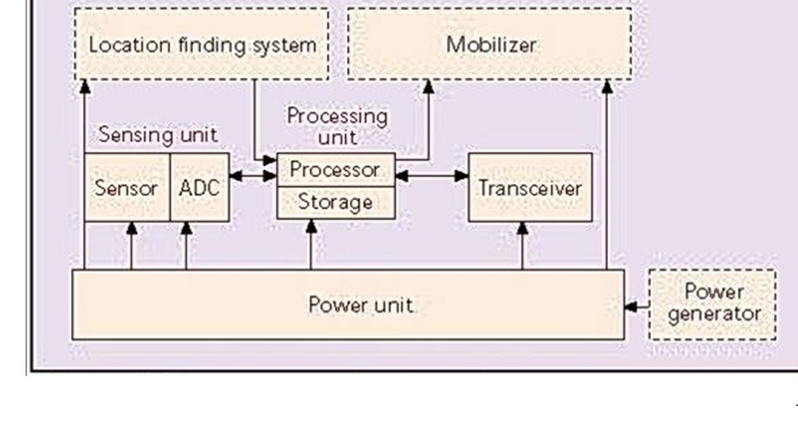
Figure 2
Data collected through a sensor are first digitized by the analog to digital converter (ADC), then processed by the local processor and transmitted through the transceiver to the next available node. A node can be packaged in various ways including embedding in ID cards, as shown in Figure 3.
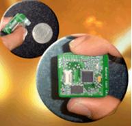
Figure 3
Some of the favorable characteristics of these nodes are… very low power consumption (enabling years of operation without the need for battery replacement), low cost (as low as a few dollars, depending on which sensors are used) and their capability for two-way communications between any node and the outside world. The particular sensor types utilized depend on the application, i.e. to establish location, motion, temperature, torque, chemical properties, oxygen level, etc.
Figure 4, shows the layout of an MRO hangar where there are many (50 in the case of Turkish Technic) stationary sensors located around the hangar walls with additional mobile nodes attached to technicians and tools.
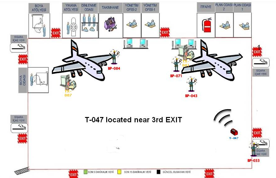
Figure 4
As soon as a technician enters the hangar work area the sensor network detects their presence.
One important application fulfilled by sensor networks is location identification. There are two ways of implementing location identification. The first approach utilizes a GPS sensor and is appropriate when working in the field and transmitting location data to the controller. The second is especially useful when working in a hangar or a closed space; this approach utilizes signal characteristics received from the stationary nodes. The signal characteristics used are RSSI (Received Signal Strength Indication) measurement of the power present in a received signal, AOA (Angle of Arrival) determining the direction of propagation of a wave and TOF (Time of Flight) the travel time of a signal from a transmitter to a remote receiver.
Using RSSI and TOF information obtained from the signals transmitted between the mobile sensors and the stationary sensors, algorithms can be developed to efficiently compute location. At Turkish Technic we can identify location within a range of 10m. This is a very high degree of accuracy given the dynamic electromagnetic environment and reflecting surfaces within the hangar.
As shown in Figure 6, outside of the closed hangar area the mobile vehicles and the other ground services equipment at the apron area of the Istanbul Ataturk Airport are monitored on a map screen in real time.
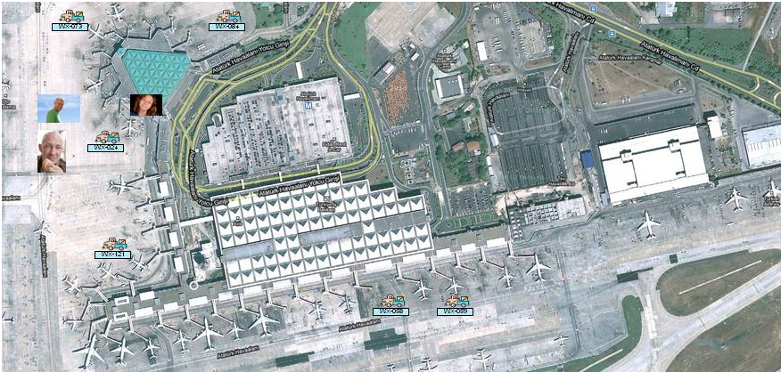
Figure 6
The portrait pictures in the Figure belong to the individuals driving the vehicles at the time of the snapshot. Other relevant maintenance information, as well as utilization statistics are monitored through the web interface. The sensor network operation extends to the apron area and the gates where some of the line maintenance is carried out.
IEEE 802.15.4 standard specifies wireless sensor network physical and medium access control (MAC) layers. The physical layer determines the wireless transmission medium, modulation and channel coding characteristics which are QPSK (Quadrature Phase Shift Keying modulation) with DSSS (Discrete Sequence Spread Spectrum). The medium access control layer specifies how the communications channel is shared among the multiplicity of transmitting nodes. Low power duty cycle ensures battery lives of several years.
Figure 4 demonstrates several ways in which wireless sensor network technology is used or planned to be used at Turkish Technic. The hangar and the surrounding area contain aircraft, technicians, tool boxes, and motorized ground service vehicles carrying technicians and equipment within the apron area. Each one of these components: technicians, toolboxes and vehicles is a part of the sensor network communicating between each other and to the outside world, in particular with the OCC (Operations Control Center).
As soon as a technician enters the work area the sensor node attached to the technician connects to the network notifying the OCC and the relevant MRO software of the presence of the technician in the area who is skilled for a particular work order, having had the appropriate training and holding the required licenses.
Figure 5 indicates the MRO software screen developed at Turkish Technic that is used to assign work orders to technicians according to whether they possess the appropriate skills. On entering the work area, the technician is added to the available staff list. The upper right table consists of the jobs that are available and open. Because the skill group of the technician is known, he can be automatically assigned to a specific aircraft and task. Then the task that was generated in the system, and for which his skills are required, is officially assigned to the technician and the related work order is transmitted to him through the sensor network.
One major contributor to reduced efficiency is time spent identifying and locating the tools that are required for a job. In this system, as soon as the technician is assigned a work order the associated equipment and tools are also identified and the location information is transmitted to the technician. Then, the work order is transmitted to the display of the sensor node or the tag of the technician. For convenience, the display may be a PDA or a tablet PC. The information received by the technician can also include the task details, required documentation to perform the task (including the relevant pages from the AMMs and IPCs) and a note of the tools required.
Having received the work order details, the technician gathers the required tools and proceeds to the particular assigned aircraft. When the task is completed, it is closed and signed off electronically by the technician. The MRO system registers the time the job has been started and completed with the appropriate approval.
Through the web-based interface, a snapshot of the work area at any given time can be viewed, including the positions of the technician’s equipment and the tools. Other examples of what might be included could be the health status of the technicians, temperature etc. There are a number of reporting capabilities that can be used such as the time spent by technicians in the hangar area and technicians’ time utilization.
This technique ensures that the technician’s time is only engaged in direct maintenance. Almost no technician time is wasted searching for maintenance documents such as AMMs, IPCs, tools and parts or work order papers; saving close to one third or half of the technician’s time as compared to the way in which a conventional operation works. In addition, daily job scheduling and assignments to the technicians are carried out efficiently and accurately based on the actual information about the availability of the technician and his skill group.
Comments (0)
There are currently no comments about this article.
To post a comment, please login or subscribe.