Articles
| Name | Author | |
|---|---|---|
| How I see IT | Michael Wm. Denis | View article |
| Plan the work or work the plan? | Tim Alden, Commercial Director, Rusada | View article |
| Human interaction with modern IT systems in aircraft maintenance | Sander de Bree, Founder and General Manager, ExSyn Aviation | View article |
| Networked MRO | Dr. Orkun Hasekioglu, R&D Projects Manager, Turkish Airlines Technic | View article |
Networked MRO
Author: Dr. Orkun Hasekioglu, R&D Projects Manager, Turkish Airlines Technic
SubscribeA new paradigm for MRO resource management and its applications at Turkish Technic. Dr. Orkun Hasekioglu, R&D Projects Manager at Turkish Airlines Technic
The concept of ‘Networked MRO’ is a new paradigm with which we are experimenting at Turkish Technic; it utilizes advanced IT technologies for innovative maintenance resource management. In a sense, it is a combination of various existing technologies. We named it ‘Networked MRO’ for reasons that will become clear as we proceed.
What is the ‘Networked MRO’ paradigm?
We define a networked MRO as an MRO facility where the individual resources are nodes in a communications network and those resources can share information with each other. A resource is, by definition, an element that participates in the MRO processes. Examples of resources are technicians, tools, parts and inventory, Ground Services Equipment (GSE), aircraft, hangar slots etc. The overall performance of the MRO operation depends on how efficiently we utilize these resources. It makes perfect sense that the more efficiently and diligently we are able to use these resources, the better will be our key performance indicators, such as work order turn-around time, cost and others.
Why is data networking needed?
We need networking because effective resource management is feasible if, and only if, proper tracking, measurement and control of these resources is established. This is possible by means of data networking. When a work order is placed we need to know the locations of the required tools, identify the technicians with suitable skill levels and determine whether they are available. Also, the defects or logs opened against the aircraft along with the most recent maintenance documents need to be accessed. All of these processes running in a typical MRO facility require data communications and communications means networking.
Benefits and objectives:
Through the networked MRO paradigm we are aiming to minimize inadequate resource utilizations. Considering that, on average, MRO expense for a typical airline will be 12% of total costs, even a 1% gain in utilization will be very significant. Our most valuable resource is the offered technician time: 60% technician time utilization (billable hours as a percentage of actual work hours) is typical. Imagine the profitability gain that could be achieved by raising the utilization to 80-90%. Based on our experience, lost time due to locating and retrieving tools, spare parts, current maintenance documents and GSE is one of the major contributors to low utilization levels. Likewise overstocked inventory ties up significant financial resources. The current industry average is around USD $2.5m worth of parts stored for each aircraft. In addition stocking expenses constitute an additional 20-25%. Networking with vendors and supply chain management service providers can enable near just-in-time stocking minimizing inventory costs.
High level system architecture
All of the indicated resources, such as aircraft, GSE, technicians, tools, vendors and flyable maintained components are parts of a very large network. The particular technologies used to establish the actual data networking may vary depending on the application. Nevertheless, they are a part of the same network and, as a result, can exchange data.
For example, aircraft share health and defect data through the VHF Aircraft Communications, Addressing and Reporting System (ACARS) link and transmit their locations, identity and heading through the Automatic Dependent Surveillance – Broadcast (ADS-B) transponders. The Ground Services Equipment and technicians participate in the network through the sensor network technology governed by the (Institute of Electrical and Electronics Engineers) IEEE 802.15.4 protocol. Tool, parts and flyable components use Radio Frequency Identification (RFID) technology as specified by the (Air Transport Association) ATA Spec 2000 chapter 9 and (Society of Automotive Engineers)SAE 5678. Suppliers and vendors receive purchase orders and returns quotations in compliance with iSpec 2200 and S1000D.
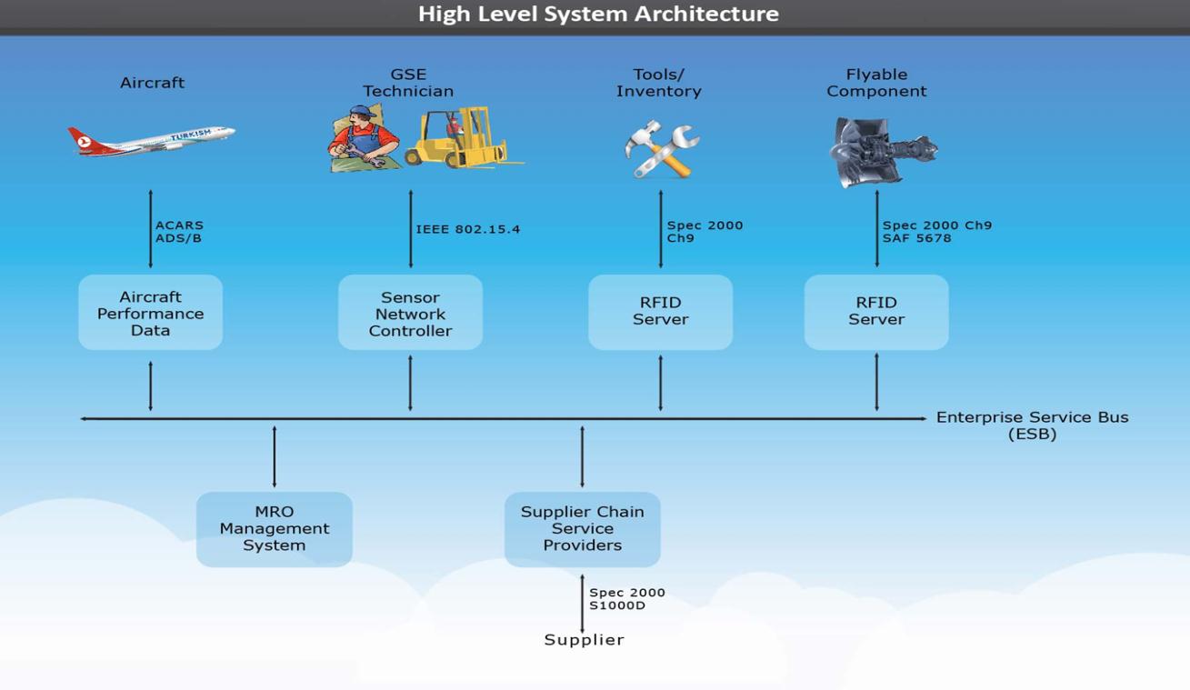
Figure 1: High level system architecture
One of the underlying technologies that enables and coordinates the data exchange is the Enterprise Service Bus (ESB) which is a typical Service Oriented Architecture (SOA) within which a number of independent processes can share information and work together through exchanged XML messages.
Conceptually, we treat all of the resources in a communications network as separate nodes that can exchange data regarding their current status and properties (status variables). An example of a communicating resource and its status variables is a technician communicating his or her location, skill level, identification and health status. A further example is the repair tools that can be automatically located and their calibration schedule verified. Similarly spare parts and their maintenance history can be accessed while the parts are on the aircraft. Each aircraft is also a node of the network. Aircraft health data and location is captured in the maintenance management system via ACARS and ADS-B.
The current ATA ebusiness functional scope covers pretty much every MRO process with which we are dealing except for the sensor network technology which is covered under IEEE 802.15.4 standard. Turkish Technic is a member of the RFID, traceability working group.
About Turkish Technic
A brief overview of Turkish Technic is appropriate here to help readers visualize the scope of the networked MRO applications we are attempting to achieve. Currently, the major part of the heavy maintenance work is done at the four hangar sites in Ankara and Istanbul. In addition there are around 60 specialized component repair shops covering components from engines and APUs (Auxiliary Power Units) to landing gear and avionics.
At present, there are around 3,600 employees on the payroll. This is predicted to increase to close to 5,000 within the next couple of years, as new projects and partnerships are put into place. In addition to the Part 145 and Part 147 certifications, Turkish Technic is also certified for Part 21 Design Organization Approval (DOA). We cover pretty much all categories of civil aircraft and component MRO including line, heavy, engine, APU and other component MRO with around 60 specialized shops. Our international customers include many airlines from Asia, Africa and Europe.
Along with these, Turkish Technic has several partnerships in the MRO sector, including, Turkish Engine Center (TEC) with Pratt and Whitney for CFM56 and V2500 engine MRO, engine nacelle and thrust reverser MRO with Goodrich, Industrial Gas Turbines MRO with Zorlu Holdings and Turkish Cabin Interior (TCI) a partnership with TAI (Turkish Aviation industries) for manufacturing of cabin interior systems.
‘Networked MRO’ applications at Turkish Technic
Having summarized the general concept of the ‘Networked MRO’ framework, a few examples from Turkish Technic will illustrate the practical approach.
Example 1: GSE and Technician Resources
The first example is GSE and technician resources management as part of the Networked MRO framework. Each piece of GSE and each technician is a node in the general data network. In this case, the physical, data link and network layers are defined by the sensor network IEEE 802.15.4 standard.
A brief description of a sensor network
A sensor network is a data communications network composed of a large number of mobile or stationary nodes that can communicate, sense and process data. Numerous sensor nodes capable of processing data and communicating information from a sensor field constitute a sensor network. The data gathered in the field through the interconnected sensors is communicated to the outside world through a gateway that is also referred to as a data sink or a coordinator.
Typically the number of nodes can be in hundreds or thousands. They can be mobile or stationary and randomly deployed. Each one of the nodes in the sensor network has sensors attached to it. The data obtained through the sensors can be locally processed in the node and then transmitted through the sensor network to the outside world. The objective is to have a very robust network that is not affected by changes in the network topology nor the addition or removal of nodes.
The data collected through the sensor is first digitized by the analog to digital converter, then processed by the local processor and transmitted by the transceiver to the next available node. The specific means of data routing is dependent on the particular network protocol implemented. A typical node can withstand years of operation without any battery replacement and costs less than a few dollars depending on which sensors are used. Two way communications is possible between nodes or with the outside world.
The sensors can measure location, motion, temperature, force or torque, chemical properties, oxygen level etc. The governing standard is IEEE 802.15.4 that defines the physical and medium access control layers.
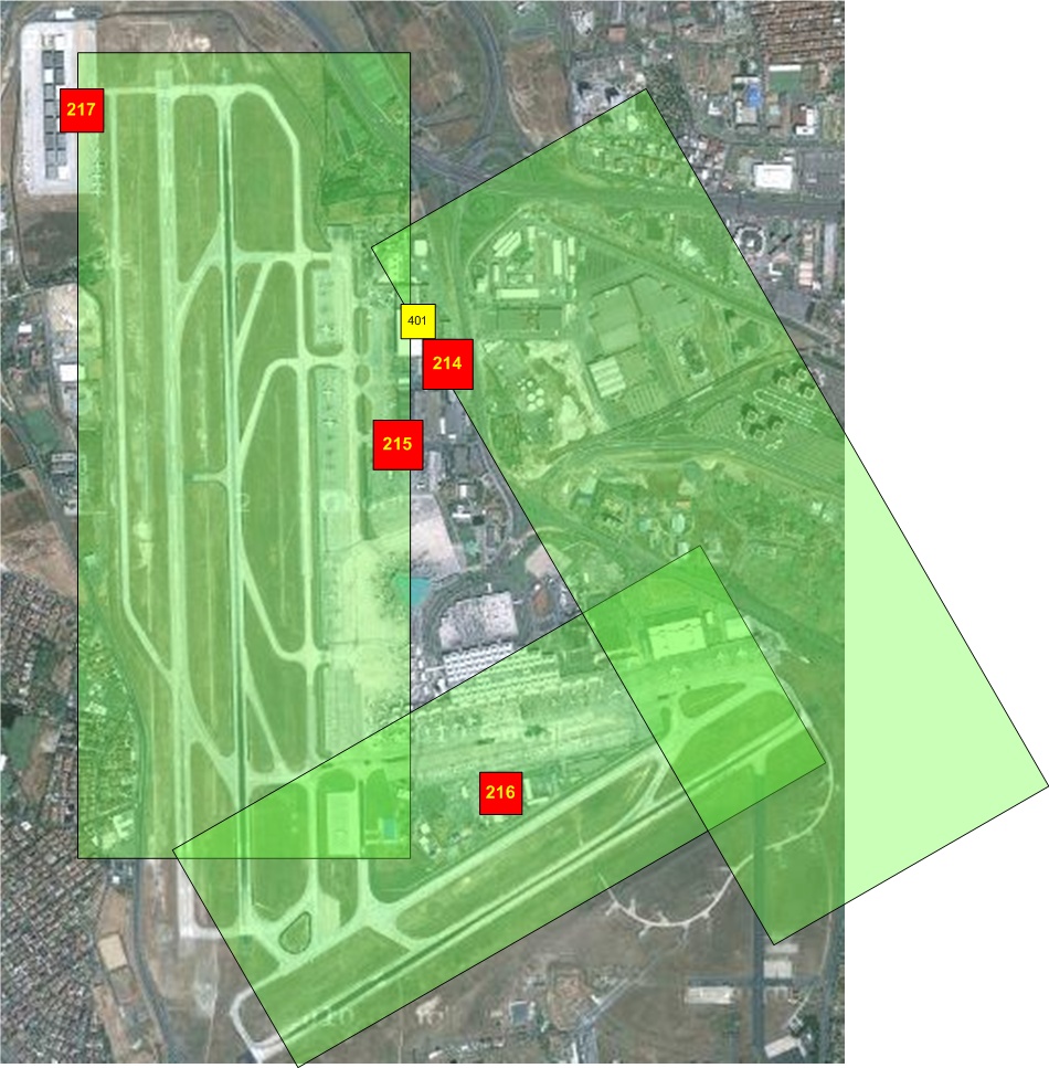
Figure 2: An aerial view of Istanbul Ataturk Airport. The shaded areas indicate the coverage of the sensor network field within the Istanbul Ataturk Airport.
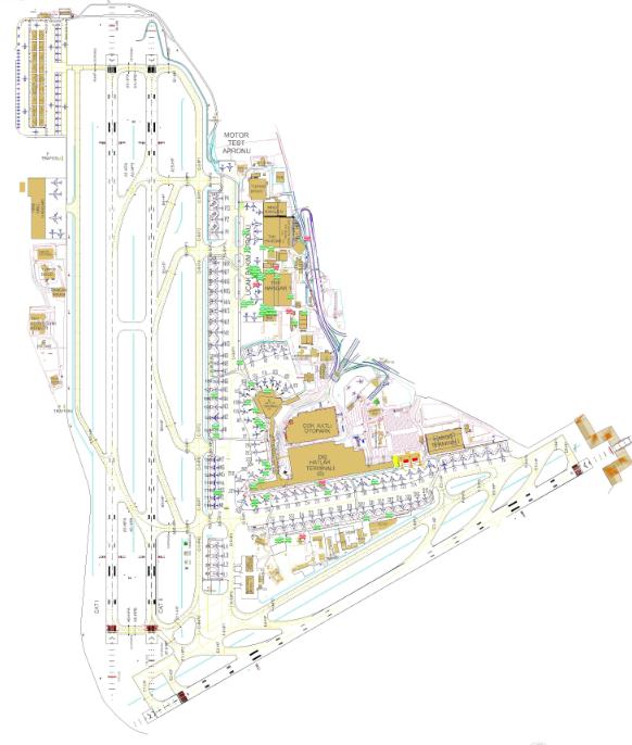
Figure 3: The graphical view of the airport as viewed from the Graphical User Interface (GUI) of the web based software.
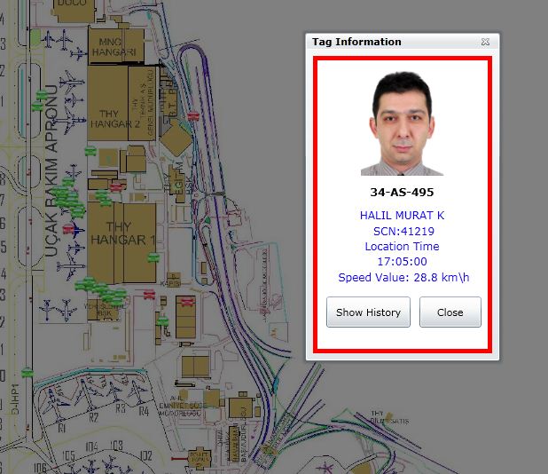
Figure 4: When any one item of equipment is clicked on, the name, identification, time, speed etc. of the current user of the GSE pops op on the screen.
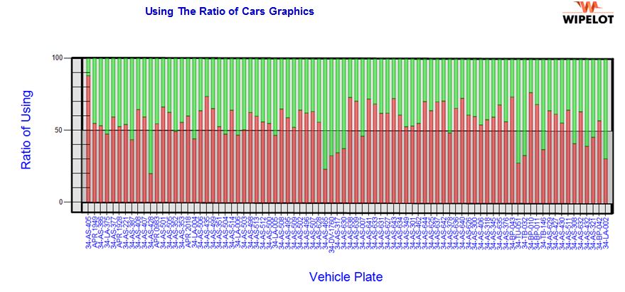
Figure 5: An example reporting output of the networked MRO environment. In this report one can access usage statistics for each piece of ground services equipment.
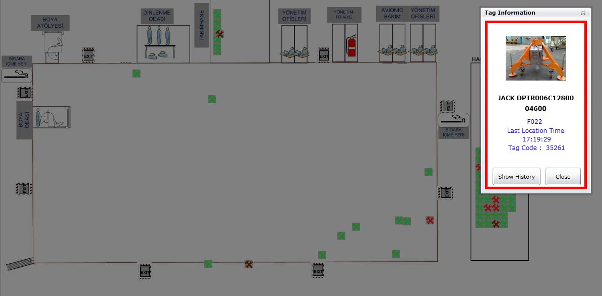
Figure 6: A snapshot from the actual GUI for one of the hangar interiors. The green and grey objects are pieces of equipment tracked in real time. When these resources are clicked on, a pop-up screen indicating the name, picture and location of the equipment appears.

Figure 7: The circled parts below are sensor nodes attached on engine carrying equipment.
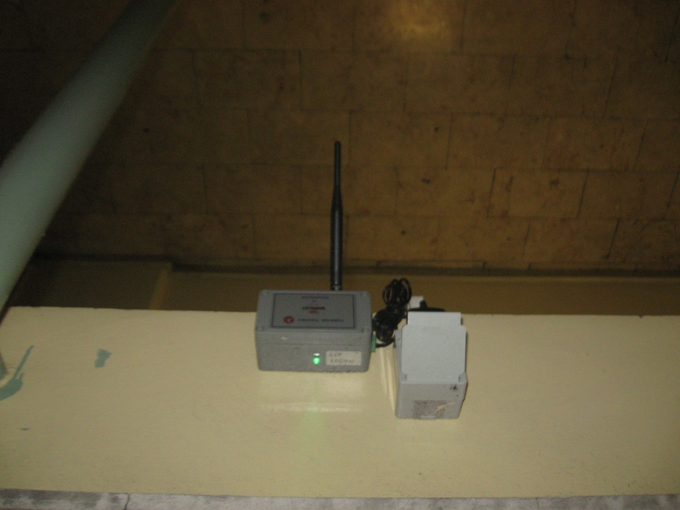
Figure 8: Close up view of an individual node device.
Example 2: Aircraft resources
The second example of the networked MRO paradigm is the aircraft resources. Again each aircraft resource is considered a node of the network that can transmit health data through ACARS and location, heading and ID information through the ADS-B transponder. Currently almost all Turkish Airlines aircraft are equipped with ACARS and ADS-B transponders.
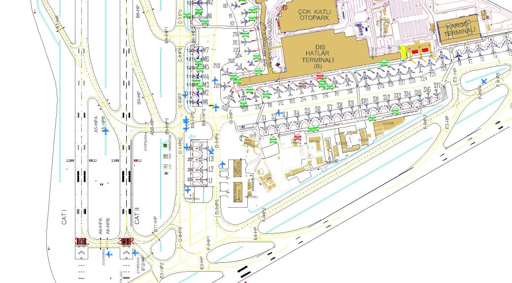
Figure 9: The received aircraft position, heading and ID data is displayed on the user interface.
Example 3: Tools and Flyable Components
The third example of the networked MRO paradigm consists of the tools and the flyable components. Each tool or flyable component that is maintained is a node in the network. In this case the networking technology we use is RFID.
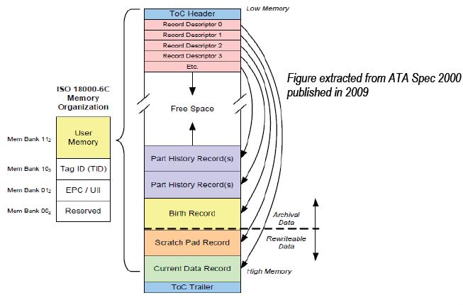
Figure 10: Each flyable component is marked with an RFID tag that is in compliance with ATA Spec 2000 and SAE 5678 standards. This is the memory organization of a tag as stipulated by Spec 2000. Starting from the birth record of the component, all the maintenance history is stored in the tag. (Courtesy ATA Spec 2000 Ch. 9)
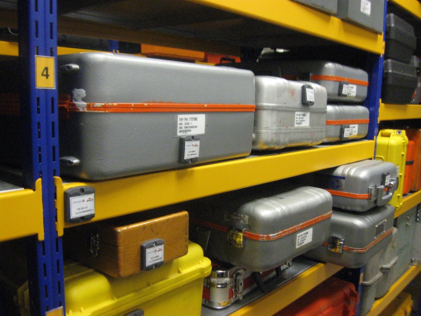
Figure 11: At the tool shop there are around 5000 tools and items of test equipment to be traced by RFID. The metal RFID tags are attached to the metal surfaces and casings of the tool sets. Each rack is marked by a tag so that the toolboxes can be associated with the rack locations.
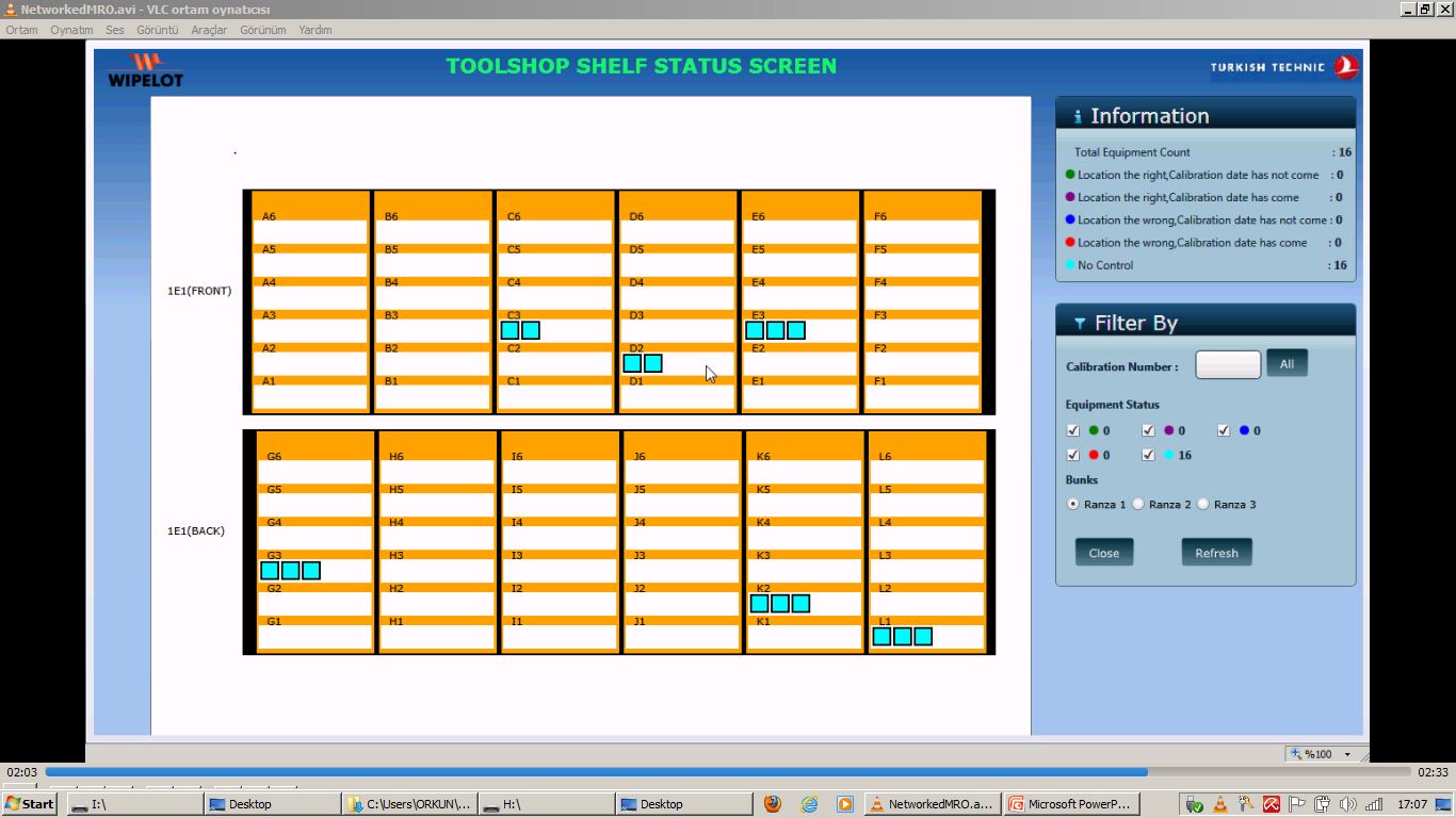
Figure 12: A snapshot view from the Networked MRO GUI. Each tool can be traced to its location on the rack and if calibration is required reports can be generated for tools with overdue calibration.
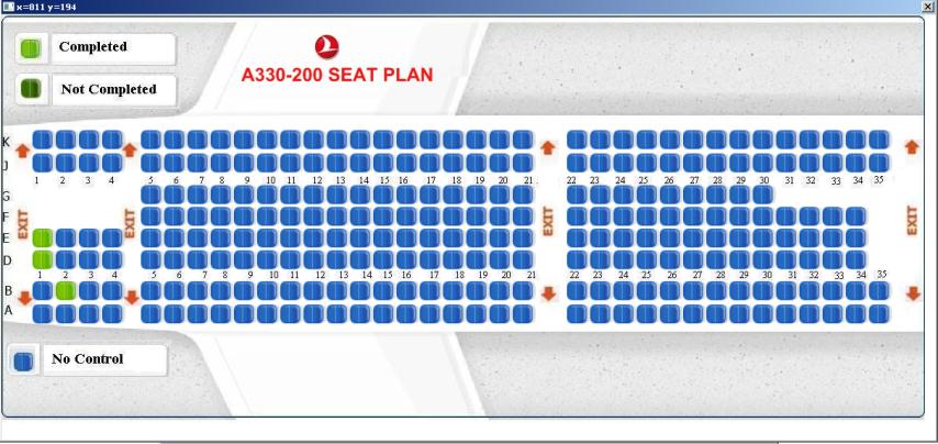
Figure 13
We also developed a separate application that runs on handheld RFID readers. Using this application the cabin interior and emergency equipment such as life vests, oxygen generators and oxygen tubes can be tracked. A reporting screen displays components that are unavailable, incorrectly located or with overdue calibrations. We have applied this to one of our A320 aircraft. Our Part 21 certification department is in the process of completing the necessary paperwork before we extend this application to the other Turkish Airlines aircraft. In this example, typical off-the-shelf RFID readers are used. However, the RFID tags are specialized to aircraft maintenance.
Example 4: Electroplating shop
We also consider the shops as part of the networked MRO paradigm.
The status of each electroplating bath including the component currently in there, the operational variables such as current, duration pH level, ion concentration and others are monitored and controlled remotely.
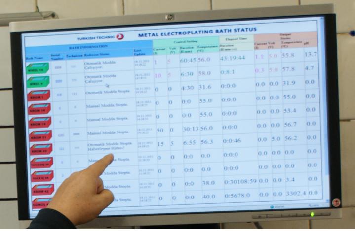
Figure 14
Conclusion:
We believe the Networked MRO paradigm summarized in this article can substantially improve the efficient and reliable use of MRO resources. We think it has already done so at Turkish Technic. Currently, aircraft, GSE and tool shop components of the networked MRO are operational. Work is continuing on the other important components of MRO resources such as technicians, suppliers and flyable components. The rate of completion will obviously depend on the amount of the development resources allocated to the project in the coming months.
We also assist other MROs and airlines to implement the technologies, hardware and software involved in this concept. If you would be interested to know more, please do not hesitate to drop me an email at ohasekioglu@thy.com.
Comments (0)
There are currently no comments about this article.
To post a comment, please login or subscribe.